

B-Tech and diploma last year project ,, SMART SENSOR PVC CAR
B-Tech and diploma last year project
SMART SENSOR PVC CAR
Note:- This project is applicable for mechanical, electrical, electronics, computer science, And other departments also.
Recommended to subscribe to my YouTube channel - AYUB CREATION
👆👆👆👆👆👆👆👆👆👆👆👆👆👆👆👆👆👆👆👆👆👆👆👆👆👆👆👆👆👆👆👆
ABSTRACT:-
From the beginning of artificial intelligence, there was a desire of having a fully automated intelligent car. Numbers of
experiments have been done and some of them were very much fruitful. As a
result, now we have intelligent smart cars. These cars are intelligent and can
take some of the decisions of their own. But they actually assist the driver for
a limited amount of time. None of them are fully automated. We think fully
automated transportation can only be possible by having a combination of intelligent
car and traffic system as well the environment like a road on which the car
actually moves.
In today's date
vehicle has become a basic need of every middle-class family. But mid-range
vehicles don't provide those facilities that every luxurious and high range
vehicle, here focus is on designing a smart car that has all facilities and
also affordable to the customer. Asper engineers point of view a smart device
is a device that is user friendly, realistic, and has a fast response also
considering the designing cost, the hardware should be less expensive and the unit
price of the designed embedded system should be cost-effective. Our design has
some excellent features such as an auto-braking system, object-avoiding system,
auto-moving system, and accident detection module. The objective of such
technologies is the reduction of the burden on drivers, improvement of the
traffic capacity, and provision of reliable and secure car functions. In
this project, we have tried to discuss a new idea for accident avoidance - a
complete solution.
 👉👉👉
👉👉👉
INTRODUCTION:-
SMART SENSOR CAR
is a mostly used intelligent system for smart car controlling. Normally a
radar or laser setup is used that allows the vehicle to slow when the front
vehicle is slowing down and speed up to the preset speed that the traffic
allows when no vehicle is in front. But these systems can only take control or
make decisions on straight roads where there is no possibility of taking
decisions about changing the route. In this project, we used Ultrasonic Proximity Sensor, and an infrared
sensor and sat a program in a microcontroller (ARDUINO UNO) so that an
intelligent network can be established which is able to take a decision for end
to end transportation without any human interaction. Now we can use the sensor
to make such a car that the car can choose its road, decide where it will be,
and where it will use the break in the road where the speed will increase, the
car can take the decision on its own. But our model car just can detect an
object, Then it can decide that it will have to turn in which direction.

Materials
used:-
In our model SMART SENSOR PVC CAR, we are used those parts and devices.
For make body of the car:-
1) PVC Pipe and pipe bands.
2) Plywood.
3) Bearings.
4) Wheel.
Provide power to the car:-
1) Battery
2) Dc Motor
Using for sensing objects:-
1) Ultrasonic Proximity Sensor.
2) Infrared sensor.
For using controlling:-
1) Microcontroller (Arduino UNO).
2) Relay circuit/motor driver
3) Switches and regulators.
4) Wire.
Any instrument will be used for any purpose:-


Bearings à Here we will
connect the wheel with bearings so that the wheel can rotate freely. wheel reducing friction and handling stress.
Resembling wheels, bearings literally
enable devices to roll, which reduces the friction between the surface of the bearing and the surface it's
rolling over.
Wheel à The wheel is used to give motion to the car the car was the move from one point to another point.


Microcontroller (Arduino UNO) à Here we are using Arduino UNO as a microcontroller that receives information from the sensor, and then the microcontroller takes a decision that the car will have to do now.


motor driver ( L293D) à It
is a motor driver which can provide bi-directional drive current for two
motors.
Switches and regulator à switch and regulator are used for manually operated the car and control car speed also
Wire à for make circuit connections.
Like à Nut and bolts, glue, PCB board, soldering iron.
welding machine, drill machine, hacksaw, or cutter machine.
Plier, screwdriver, and hammer
A computer or pc. Etc…………
NUT AND BOLTS/ GLUE à used for fixing the parts.
PCB
BOARD à connect the small electronic component
together make a circuit.
SOLDERING
IRON à fixing
the electronic component.
DRILL
MACHINE à used
for some drilling operation.
HACKSAW
OR CUTTER MACHINE. à used for some cutting operation.
PLIER/SCREWDRIVER à using for tight the nut and bolts
HAMMER
à for hammering something
A computer or pc à for upload the program in Arduino
Working Principle:-
The
smart sensor car uses ultrasonic sensors and Infrared
sensors for its movements. A microcontroller of the 8051 families is used to
achieve the desired operation. The motors are connected through the motor driver IC
to the microcontroller. The ultrasonic sensor is attached in front of the robot.
And Infrared sensor sensors bottom of the car. Whenever
the robot is going on the desired path the ultrasonic sensor transmits the
ultrasonic waves continuously from its sensor head. Whenever an obstacle comes
ahead of it the ultrasonic waves are reflected back from an object and that
information is passed to the microcontroller. The microcontroller controls the
motors left, right, back, front, based on ultrasonic signals. In order to
control the speed of each motor, pulse width modulation is used (PWM). And The Infrared sensor is used for path detection. When the right sensor is not detected in the
curve line, the microcontroller activates the left motor to turn left until the
signal from the right sensor. Once the signal is detected right sensor, the two motors
are activated to go forward. When the line ends at that time the robot
reverse at 180 and turns back to the same place.
Since we do not have any system to rotate the car handle, we need to move the car so motor off and on to turn the car left and right. When the left side's motor is off and the right side motor is on the car will be turned on in the anticlockwise direction. When the right side motor is off and the left side's motor is on the car will be turned in a clockwise direction. It’s also operated by a switch manually but in cash of our modal smart car motor off on control by microcontroller ATMAGA328P (ARDUINO UNO). This car speed, brake, and other functions are also controlled by the sensor, ic, and microcontroller.


WORKING OF ULTRASONIC SENSOR

The HC-SR04 Ultrasonic Module has 4 pins, Ground, VCC, Trig and Echo. The Ground and the VCC pins of the module need to be connected to the Ground and the 5 volts pins on the Arduino Board respectively and the trig and echo pins to any Digital I/O pin on the Arduino Board.
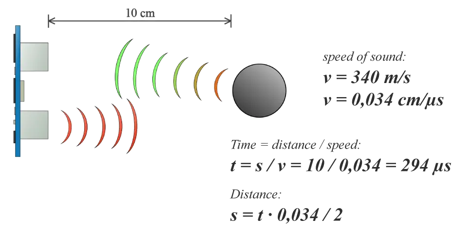
In order to generate the ultrasound, you need to set the Trig on a High State for 10 µs. That will send out an 8 cycle sonic burst which will travel at the speed sound and it will be received in the Echo pin. The Echo pin will output the time in microseconds the sound wave traveled.

For example, if the object is 10 cm away from the sensor, and the speed of the sound is 340 m/s or 0.034 cm/µs the sound wave will need to travel about 294 u seconds. But what you will get from the Echo pin will be double that number because the sound wave needs to travel forward and bounce backward. So in order to get the distance in cm, we need to multiply the received travel time value from the echo pin by 0.034 and divide it by 2.

IR SENSOR
An IR sensor is a
device that detects IR radiation falling on it. Proximity sensors (used in
touchscreen phones and edge-avoiding robots), contrast sensors (used in line
following robots) and obstruction counters/sensors (used for counting goods and
in burglar alarms) are some applications involving IR sensors.
Principle of Working
An IR sensor consists
of two parts, the emitter circuit, and the receiver circuit. This is
collectively known as a photo-coupler or an optocoupler.
The emitter is an IR LED and the detector is an IR photodiode. The IR photodiode is sensitive to the IR light emitted by an IR LED. The photo-diodes resistance and output voltage change in proportion to the IR light received. This is the underlying working principle of the IR sensor.

The type of incidence can be direct incidence or indirect incidence. In direct incidence, the IR LED is placed in front of a photodiode with no obstacle in between. In indirect incidence, both the diodes are placed side by side with an opaque object in front of the sensor. The light from the IR LED hits the opaque surface and reflects back to the photodiode.
IR sensors find a wide variety of applications in various fields. Let’s take a look at a few of them.IR sensors detect the color of the surface underneath it and send a signal to the microcontroller or the main circuit which then takes decisions according to the algorithm set by the creator of the bot. Line followers employ reflective or non-reflective indirect incidence. The IR is reflected back to the module from the white surface around the black line. But IR radiation is absorbed completely by black color. There is no reflection of the IR radiation going back to the sensor module in black color.
PROCEDURE
Step 1: What You Will Need
At first, we need to do buy all the required materials.
è Here we need the materials that we have
already mentioned above (in the topic of
“Materials used”)
And have to take the equipment/tools also.
è
soldering
iron. Welding machine, drill machine, hacksaw or cutter machine. Plier,
screwdriver, and hammer…
Step 2: Prepare the car Base
First, cut the
PVC pipes according to their size. Then we will create the car structure across
the pipes with glue through the pipe band, Then cut
the plywood design like that. Then it will be added to the structure of the PVC
pipes under the screw and bolt as support below
Step 3:
Put the Hardware Parts on It
we will set the
bearings to a piece of small plywood, We will put the bearings in the usual place with the structure of the car.
Then we will pass
the wheel shaft through the bearing and connect with the motor shaft.
Place the motor,
battery and all other hardware parts.
Check all structure
and hardware parts carefully, If they are not in place, they should be
fixed again and nuts should be tightened.
Tip: You can also open holes for the motors and
battery cables, and also place circuits.
Step 4: The "eyes" of I our car
This means
that the sensor in the eyes of our cars. The sensor is an important thing for our
car, so be very cautious when planting the sensor and properly fix them in the right place with glue and screw.
Step 5:
Work on the car wiring system
After placing all the equipment and hardware parts, checked properly, and then start doing wiring through wires. as par the electric circuit diagram.
After complete wiring, check carefully
Step 6: The Code
At the end of all
work we need to program a car microcontroller (Arduino UNO). To control the car. Hare the block diagram
for coding

CODS
//Pin numbers definition
const int RELAY1 = 7;
const int RELAY2 = 8;
const int RELAY3 = 9;
const int RELAY4 = 10;
const int IRL = 11;
const int IRR = 12;
const int trigPinFront = 1;
const int echoPinFront = 2;
const int trigPinLeft = 3;
const int echoPinLeft = 4;
const int trigPinRight = 5;
const int echoPinRight = 6;
//Variables for Ultrasonic Sensors
long durationFront;
int distanceFront;
long durationLeft;
int distanceLeft;
long durationRight;
int distanceRight;
const int minFrontDistance = 30;
const int minSideDistance = 20;
const int stuckDistance = 10;
void stopCar () {
digitalWrite(RELAY1,
LOW);
digitalWrite(RELAY2,
LOW);
digitalWrite(RELAY3,
LOW);
digitalWrite(RELAY4,
LOW);
}
void goForwardFull () {
digitalWrite(RELAY1,
HIGH);
digitalWrite(RELAY2,
LOW);
digitalWrite(RELAY3,
HIGH);
digitalWrite(RELAY4,
LOW);
}
void goLeft () {
digitalWrite(RELAY1,
LOW);
digitalWrite(RELAY2,
LOW);
digitalWrite(RELAY3,
HIGH);
digitalWrite(RELAY4,
LOW);
}
void goRight () {
digitalWrite(RELAY1,
HIGH);
digitalWrite(RELAY2,
LOW);
digitalWrite(RELAY3,
LOW);
digitalWrite(RELAY4,
LOW);
}
void goBack () {
digitalWrite(RELAY1,
LOW);
digitalWrite(RELAY2,
HIGH);
digitalWrite(RELAY3,
LOW);
digitalWrite(RELAY4,
HIGH);
}
void sensorRead () {
//Read front sensor value
digitalWrite(trigPinFront,
LOW);
delayMicroseconds(2);
digitalWrite(trigPinFront,
HIGH);
delayMicroseconds(10);
digitalWrite(trigPinFront,
LOW);
durationFront
= pulseIn(echoPinFront, HIGH);
distanceFront
= durationFront * 0.034 / 2;
//Read left sensor value
digitalWrite(trigPinLeft,
LOW);
delayMicroseconds(2);
digitalWrite(trigPinLeft,
HIGH);
delayMicroseconds(10);
digitalWrite(trigPinLeft,
LOW);
durationLeft =
pulseIn(echoPinLeft, HIGH);
distanceLeft
= durationLeft * 0.034 / 2;
//Read right sensor value
digitalWrite(trigPinRight,
LOW);
delayMicroseconds(2);
digitalWrite(trigPinRight,
HIGH);
delayMicroseconds(10);
digitalWrite(trigPinRight,
LOW);
durationRight
= pulseIn(echoPinRight, HIGH);
distanceRight
= durationRight * 0.034 / 2;
}
void setup() {
pinMode(RELAY1,
OUTPUT);
pinMode(RELAY2,
OUTPUT);
pinMode(RELAY3,
OUTPUT);
pinMode(RELAY4,
OUTPUT);
pinMode(IRL,
INPUT);
pinMode(IRR,
INPUT);
pinMode(trigPinFront,
OUTPUT);
pinMode(echoPinFront,
INPUT);
pinMode(trigPinLeft,
OUTPUT);
pinMode(echoPinLeft,
INPUT);
pinMode(trigPinRight,
OUTPUT);
pinMode(echoPinRight,
INPUT);
}
void loop()
{ int IRL=digitalRead(11);
int
IRR=digitalRead(12);
if
(IRL==0 && IRL==0){
if ((distanceLeft > distanceRight )
&& (IRL==1 && IRL==0)){
if ((distanceLeft <= distanceRight)
&& (IRL==0 && IRL==1)){
if
((distanceLeft <= distanceRight ) && (IRL==1 && IRL==0)){
if
((distanceLeft > distanceRight) && (IRL==0 && IRL==1)){
if
((distanceFront <= minFrontDistance) || (distanceLeft <= minSideDistance)
|| (distanceRight <= minSideDistance)) {
if
((distanceLeft < stuckDistance) || (distanceRight < stuckDistance) ||
(distanceFront < stuckDistance)) {
stopCar ();
delay(5000);
}
else if
((distanceFront <= minFrontDistance) && (distanceLeft <=
minSideDistance) && (distanceRight <= minSideDistance)) {
goBack();
delay(5000);
}
else
if
(distanceLeft > distanceRight ){
if
(IRL==0 && IRL==1){
if
((distanceLeft > distanceRight ) && (IRL==0 && IRL==1)) {
goLeft();
delay(5000);
}
else
if
(distanceLeft <= distanceRight){
if(IRL==1
&& IRL==0){
if
((distanceLeft <= distanceRight) && (IRL==1 && IRL==0)) {
goRight();
delay(5000);
}
else
if
(IRL==1 && IRL==1){
goForwardFull();
}
else
goForwardFull();
}
}
}
}
} }}}}}}
COST ESTIMATION:-
Here we are just making a model of SMART SENSOR PVC CAR, so we are taking this as a plan of expenditure.


Post a Comment